Biomass CompressorPlease help support this open source work by becoming a True Fan The Biomass Compressor aka The biomass-powered, computer-controlled, hydraulically-operated synthesis gas compressor!
At each step in this process, we look for research directions which offer the potential of near-term benefit. For example, we started to tackle the challenge of getting a 3/4 ton work truck running on woodgas by breaking the work into discrete steps such as:
It's counter-intuitive, but often it works best to tackle this sort of work from end to start. Accordingly, the step we chose to tackle first was actually the third step on this list; learning how to get a work truck to run efficiently and reliably on a gaseous fuel. In general, there are two commonly used liquid transportation fuels (gasoline and diesel), and two gaseous fuels (compressed natural gas and liquified petroleum gas, commonly referred to as CNG and LPG respectively). The step we chose to tackle first involved learning how to get a work truck that had been built to run on gasoline to run instead on a gaseous fuel. While this was work that was new to us, converting gasoline engines to run on propane is a well established practice. We were able to purchase mass-produced components that performed each of the tasks involved, install them and have been running on either gasoline or propane for some years now.
Sometimes we run the work truck on gasoline, and sometimes on propane, depending on current price and availability, but either way, our overall cost of transporting heavy supplies to our community has been reduced, thereby allowing us to use the funds saved to underwrite the next stage of the research. The second step in this section of the B2M project, the production of a gaseous fuel capable of powering the work truck, can be broken down further into two discrete steps:
Throughout this work, we've had the privilege of collaborating with Jim Mason and the crew of All Power Labs in Berkeley, CA. Their efforts have been focused on developing an open-source approach to the challenge of converting most any form of biomass into a gaseous fuel capable of powering an internal combustion engine. Their initial work is embodied in their Gasifier Experimenter's Kit, and you can Click Here to read about our involvement with the GEK concept. While the GEK is a rapidly maturing design for stationary applications, the gas it produces, traditionally called "producer gas" is about 50% nitrogen. That's not a problem when the gas is immediately sucked into an engine and burned, but it's a big problem for anyone who wants to compress the gas and use it further down the road. Since it takes energy to compress a gas, compressing a mix of gases that's only 50% combustible is a losing proposition from the start. Adding to the problem, high-pressure storage tanks aren't cheap, and it would take twice as large a tank to go a given distance on producer gas as compared to a gas that was fully combustible. The route we're taking to address this challenge consists of two parts:
There are a wide range of different gasification designs, as well as a range of different ways to process producer gas depending on the desired endpoint. Auto-thermal steam reformation uses the thermally counter-balancing inputs of oxygen and steam to transform charcoal into a gas consisting solely of hydrogen and carbon monoxide. Charcoal is readily oxidized to a glowing, hot ember in the presence of pure oxygen, and steam is readily broken down into hydrogen and carbon monoxide by contact with glowing hot charcoal. By balancing the ratio of steam and oxygen introduced into the insulated retort, charcoal can be readily converted into a fully combustible fuel in accordance with the formulas, 2C + O2 => 2CO + heat
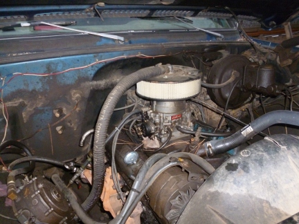
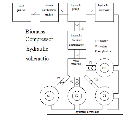
The import of all this is that at the center of the current work of the B2M project lies the challenge of creating a biomass-driven, computer-controlled, hydraulically-activated compressor designed to compress first air, and when that's mastered, synthesis gas to various pressure levels. Even before we formally tackle the challenge of converting syngas into a liquid fuel suitable for current flex-fueled vehicles, the Biomass Compressor will enable us to reap the immediate benefit of being able to forego the need to purchase fuel for our work truck, or for any other vehicle set up to use CNG or LPG fuels.C + H2O + heat => H2 + CO The Biomass Compressor uses gasified biomass (in our case it's in the form of chipped forest waste) to power an internal combustion motor which in turn drives a hydraulic pump. The pressurized hydraulic fluid is then used to operate a bank of hydraulic cylinders which in turn operate the cylinders which do the actual compression of the various gases used in the B2M project. Here's a schematic description of the first section of the Biomass Compressor.
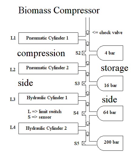
And here's a schematic description of the second side‒the compressor side‒of the Biomass Compressor. Each of the cylinders in the compression side are connected to the working arm of the hydraulic cylinders shown in the first schematic. The various cylinders differ in diameter according to the output pressure needed in each stage of the compressor. Note: 1 bar is roughly equal to one atmosphere of pressure. Each stage of the Biomass Compressor increases the pressure by a factor of four going from 1 bar to 4 bar (60 psi), then to 16 bar (250 psi), 64 bar (1,000 psi), and finally to 200 bar (3,000 psi). While the compressor could achieve a higher end pressure, there's little incentive to do that since 200 bar is the pressure used to fill the type of fuel tank used in natural gas (CNG) fueled vehicles.
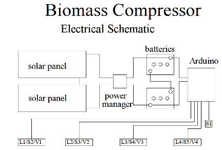
Below is a diagram of the electrical components of the Biomass Compressor. The system voltage is 24 VDC. Two photovoltaic panels wired in series to feed a power manager which in turn charges two 12 VDC deep-cycle batteries.
The limit sensors are simple SPST microswitches which close when a cylinder piston has completed a compression cycle. The pressure sensors generate an analog output that's proportional to the pressure coming out of each stage, and are designed by the manufacturer for different pressure ranges:
Parts List
Project Work Log
|