Hydraulic CompressionAn Initial LookThe science of compression is key to the success of any biomass-to-fuel project. The various types of reactors involved can all be fairly described as devices which contain gases as they flow from areas of high pressure to low, and as they flow are converted from one form into another. There are a variety of mechanical ways to compress a gas; the most common being the piston compressor. This is a machine that uses a reciprocating piston to draw a gas such as air into a chamber, and then compresses it into some form of holding tank. A piston compressor works well enough producing small volumes of air at up to 8 bar (120 psi), but it's generally unsuitable for use with problematic gases such as carbon monoxide, ammonia, hydrogen or oxygen. A key problem with piston based compressors is "blow by." As the piston moves up and down inside a metal cylinder, a series of piston rings create a dynamic seal that, while working effectively enough, still leaks at least a little. When what's being leaked is air, that's not a big problem, but when combustible gases are leaked into air, the resulting mixture can be explosive. For a description of how a reciprocating compressor works, Click Here.
Hydraulic Compression For B2M we need something much smaller, and less technologically demanding, which brings us to a combination of pneumatic and hydraulic compression. Both perform the same function; a key difference lies in whether the acting force in the compressor is a gas (pneumatic) or a liquid (hydraulic). A common way that the pressure of a gas is measured is in terms of the ratio of the pressure of the gas to standard atmospheric pressure. A pressure of 1 bar is essentially equal to one atmosphere. Pneumatic cylinders are designed to operate up to 16 bar, while hydraulic cylinders commonly operate at pressures of 200 bar and greater. Oxygen is an example of a gas that's routinely stored at greater than 200 bar. For B2M, we'll be compressing gases in stages, with each stage involving a compression ratio of four to one. The first stage will compress from one to four bar, and the second stage will handle compression from four to sixteen bar. This range is sufficient for most of the work involved in converting woody biomass to methanol. Depending on the chemical path taken and the products desired (methanol is only one of many useful products that can be made from syngas), it may be desirable to work with higher pressures. In that case, a third stage would compress gas from sixteen to sixty-four bar, and if more compression was desired, a fourth stage would handle compressing gases from sixty-four to two hundred bar. For example, the fuel tanks on city buses and private cars that run on compressed natural gas (CNG) are designed to operate at pressures up to 250 bar (~3,500 psi). How It Works There are a variety of ways that a hydraulic compressor can be configured depending on whether you're using a pair of connected cylinders or a double action cylinder that's been set up to work alone. In its fullest configuration, such a compressor would consist of four stages with a storage tank located in between each stage of the compressor. In our first stage, we'll be using a small hydraulic cylinder to operate a larger pneumatic cylinder. The small hydraulic cylinder has a 2" diameter piston and drives a pneumatic cylinder with a 6" diameter piston. The pressure exerted by one cylinder against another is automatically multiplied or divided by the relative areas of the pistons. While the diameter of the larger piston is three times that of the smaller, what counts is the relative surface areas of the pistons. Since surface area is a function of the square of the radius, a 6" piston has nine times more surface area than a 2" piston.
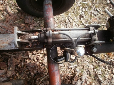
We'll use that sort of differential to step up or step down the pressure put out by our hydraulic pump in much the same way that an electrical transformer is used to step up or step down voltage. The local power company's overhead electrical power lines deliver energy to Windward at around 7,200 volts. One way to think of voltage is as an expression of how much electrical pressure a circuit has, and that's a lot. In order to get that voltage down to where it can serve our needs, the line voltage is fed into a transformer which steps it down to the 240 volt circuits that power our various buildings. Similarly, we'll be configuring our hydraulic compressor in a variety of ways in order to match up the various power requirements of each stage. One type of hydraulic equipment that we use often here at Windward is our wood splitter. In this case, an internal combustion engine turns a hydraulic pump which then feeds pressurized oil to a hydraulic cylinder. As the pressure builds up in the cylinder, the cylinder's piston is pushed out until it makes contact with the wood that we're wanting to split. As the wood resists, the motor builds up pressure in the cylinder. When that pressure builds up enough, the wood splits. In a hydraulic compressor, when enough pressure builds up, the gas at the other end is compressed. When the pressure of the gas being compressed exceeds the pressure in the next storage tank, it moves out, through the check valve and into the next stage. That's it; repeat as needed. A huge advantage that hydraulic compression offers us is the ability to compress a small amount of gas to high pressures at precisely the time that it's needed. In the first stage (1 to 4 bar) we'll use a 2" hydraulic cylinder to push a 6" pneumatic cylinder (a 9:1 power ratio). In the second stage (4 to 16 bar), we'll use an identical 2" hydraulic cylinder to push a 4" pneumatic cylinder (a 1:4 power ratio). Stage Three The third stage will involve a different approach. Instead of having one cylinder push another, everything will be happening inside a single cylinder. A cylinder that's capable of exerting force in opposite directions is referred to as a "double action" cylinder. Pressure is applied to one side of the internal piston head to move the piston shaft one direction, and then on the other side of the piston head to move it in the opposite direction. For the third stage, a double acting hydraulic cylinder will be mounted vertically with hydraulic fluid acting below the piston head, and with the gas being compressed in the space above the piston head.
Compressed gas from ST2 (the storage tank located in between stages two and three) will flow through the check valve and into the top of the cylinder. This will push the piston head downward thereby pushing hydraulic fluid out the lower inlet, through the control valve and back into the reservoir. The third stage of compression will start when a sensor indicates that the pressure above the piston head has reached 16 bar. When that happens, the control computer will tell a solenoid-controlled valve to route compressed hydraulic fluid from the pump to the bottom section of the cylinder. As the hydraulic pressure on the bottom of the piston head increases, at some point the pressure below the piston head will become greater than the pressure on the top of the piston head, the piston will start to rise. This will compress the gas on top of the piston head, and bring things back into balance. Only they won't strike a balance just yet because as hydraulic fluid continues to flow into the bottom portion of the cylinder, the piston head will keep rising and continue to increase the pressure of the gas on top of the piston. As soon as the pressure in the top half of the cylinder exceeds the pressure in ST3 (the storage tank located in between stage three and stage four), the gas will flow out of the upper half of the cylinder, through the check vale, and into ST3. When the piston head reaches the top of the cylinder, as indicated by the shaft running into a microswitch, the control computer will turn off the seloniod valve, thereby stopping the flow of pressized fluid into the cylinder. When the valve resets, it will allow the fluid in the bottom half of the cylinder to flow out, through the selonid valve and back into the reservoir. Stage 3 will raise the pressure in the third Storage Tank to 64 bar (~ 1000 psi). In order to go higher, we'll have to do something similar to stage two, but in reverse. Driving the Compressor One of the hallmarks of the B2M Project is a determination to emulate the way that nature pursues a goal through a series of parallel paths, varying the primary route depending on unfolding circumstances. In this case, we'll be producing the hydraulic pressure driving the compression part of B2M in variety of ways; three examples are:
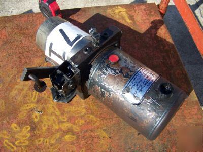
The first route has the advantage that it can operate solely under computer control. As the photovoltaic panels convert sunlight into electricity, the power manager will use that energy to charge our 24 VDC battery set. When the batteries are fully charged (i.e. the battery voltage exceeds 28 VDC), the electricity being produced by the panels has to be diverted somewhere so that it doesn't over-charge and damage the batteries. By converting that electrical energy to hydraulic pressure, and then using that to compress gases, we expand our ability to store energy ten-fold without having to rely on a large bank of lead-acid batteries. One advantage of the second route is that we'd be using woodgas to power the woodgas storage compressor. Another is that the internal combustion engine/hydraulic pump combination would generate a lot more compression than the power pack would. A disadvantage would be that someone would have to oversee the operation, i.e. it won't run unattended. The primary advantage of the third route is that it utilizes the exhaust from the project's solar-powered steam-to-electricity component. A significant portion of a rural community's energy needs will be in the form of electricity, and a traditional steam engine driving an axial flux alternator is a good match. Click Here to see an example. In the video, the red assembly being driven by the steam engine is an axial flux alternator. The spent steam coming out of the steam engine needs to be condensed in order to return that water to the boiler, and a condenser based on Newcomb's atmospheric engine design can conserve water and compress hydraulic fluid at the same time. Back to Stage Four Those various compression operations will be described separately, but what they have in common is that they'll pressurize hydraulic fluid to 128 bar (~2,000 psi). Stage Four will use a 4" diameter hyraulic cylinder to drive a 2" hydraulic cylinder that will boost the gas pressure from 64 bar to a final pressure of over 200 bar (~3000 psi). When air is compressed to over 200 bar, cooled to room temperature, and then allowed to decompress, the change in pressure causes the temperature to drop to the point where the air turns into a liquid. As a result, liquid air is one of the useful products that can be produced by a four stage hydraulic compressor. Liquid air can even be used as the ultimate "no emmisions" vehicle fuel as demonstrated by the University of Washington's Cool Car! Another use for a multi-stage hydraulic compressor would be to fill the fuel tank of a car or truck that had been modified to run on compressed natural gas, only in this case, instead of natural gas, it would be fueled with nitrogen-free producer gas. At that point, the B2M Project will have demonstrated the ability to convert woody biomass into a fuel that can be used in commercially-available, over-the-road vehicles. After passing that milestone, we'll shift our focus to the challenge of converting nitrogen-free producer gas into a liquid fuel that can be used in vehicles such as the average personal vehicles that most people already drive. For more information about the biomass-fueled compressor we're building, Click Here. A Patented Example of a Hydraulic Compressor Click Here to view US Patent 5,622,478. |

