December 2013 Update
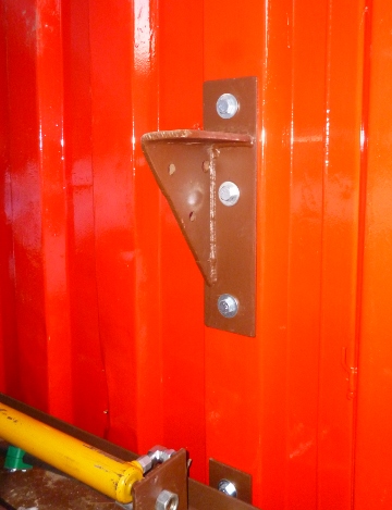
December 15, 2013 Now that we have the compressor's shelter in place, it's time to start assembling the various components. First, we'll focus on Stage 1 which will compress atmospheric air into the 60 psi range. Given the size of the pneumatic cylinder we're using for the bellows on Stage 1, we made the support rail out of a ten foot long section of 8"x3" U-channel. With the rail alone weighing in at more than a hundred pounds, and given the vibratory nature of the work, ordinary brackets wouldn't be strong enough, so we fabricated what we needed out of 1/4" thick steel.
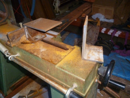
The brackets were tailored to suit the rails they support; 8" for Stage 1 and 6" for Stage 2. They're bolted to the side of PowerLab with 1/2 bolts using nylock nuts, so we've every reason to be confident that they'll bear the load. With the rail in place, the next step was to mount up the two cylinders. To hold the weight two sets of heavy steel brackets were tailored to suit the rails they support; 8" wide brackets for Stage 1 and 6" wide brackets for Stage 2. There's a second type of bracket involved in assembling these first two stages; the brackets that connect the cylinders to the rail. These were fabricated from 1/4" thick 4"x3" "L" angle cut to 3 1/4" lengths.
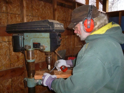
Two 3/8" holes were drilled in the base of each bracket so that they could be mounted to the rails. Then, a hole that was particular to the specific function of that specific bracket was drilled in the vertical face of the bracket using a hole-saw. For example, the drive cylinders have a 3/4" fine threaded stud. Below is a pic of Walt using a hole-saw to create the mounting hole. [Note: some of the things to keep in mind when using a hole-saw is (1) to use a drill press, (2) set it for a slow cutting speed and (3) use frequent squirts of oil to ensure that the teeth of the saw don't over heat and lose temper.]
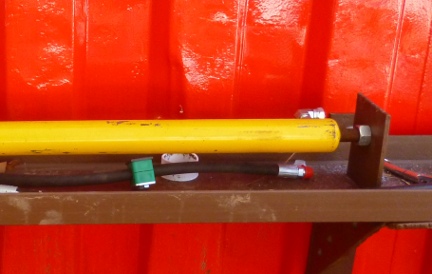
And here's a pic of that bracket installed on the base end of Stage 1's drive cylinder.
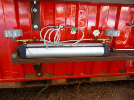
Another detail that needed to be addressed involved joining together the output from each end of the bellows cylinder into a single line that would carry the compressed gas from the output of Stage 1, to the holding tank, and from there on to the input section of Stage 2. The option we went for was stainless steel braided water supply lines in the hope that the steel braid would help dissipate heat from the newly compressed gas.
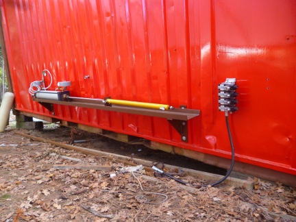
That pretty much completes the work on Stage 1 for now. The next work on Stage 1 will come when we hook up the hydraulic pressure hoses that will power the working cylinder (the yellow cylinder), but there are other parts of the compressor we'll be working on before that happens.
|