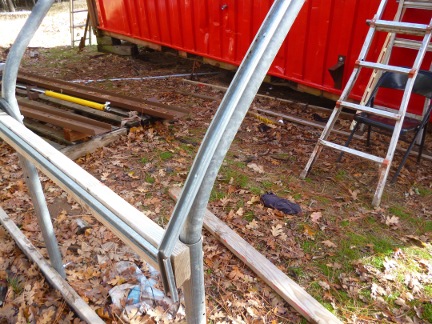
Floating FoundationDecember 26, 2013 Initially the energy needed to drive the Biomass Compressor will come from the combustion of wood gas in an ordinary internal combustion engine, the same type of engine we use to power our hydraulic wood splitter. In turn, the engine will convert the energy in the gas into hydraulic pressure by turning a hydraulic pump. The pressurized hydraulic fluid will then operate the compressor's various drive cylinders. Internal combustion engines vibrate when they run, something that's especially true for single cylinder engines. Whatever the engine is mounted on needs to be able to absorb that vibration without being damaged. One way this is done is to create a floating foundation for the motor that's at least ten times more massive than the motor itself. Like most of Windward, the area where we'll be assembling the Biomass Compressor is sloped ground, so a notable amount of leveling had to be done. The trick is to start at the lowest point, and level from there using a mattock and a leveling shovel (it's also sometimes called a transfer, plaining or grading shovel). The shovel that most people are familiar with has a rounded bottom; a leveling shovel has a flat bottom and can be used to create a level, flat-bottomed trench.
The trick is to start by using a long level to get a clear concept of what level looks like in that location. Once you have a few feet of trench dug, you check it with the level, make adjustments as needed, and then away you go. Once that level trench is long enough, you can lay the first railroad tie in place. Then, working from each end of that initial tie, you create perpendicular trenches, the bottoms of which are level with the top of each end of that first tie. When those two short trenches are in, then it's a simple matter of closing the rectangle. To finish the work, you need to go back and dig a deeper trench for the second tie, excavating enough dirt so that it's deep enough that it's top is level with the first tie. When you're done, you should have two 8' railroad ties that are level front to back and side to side.
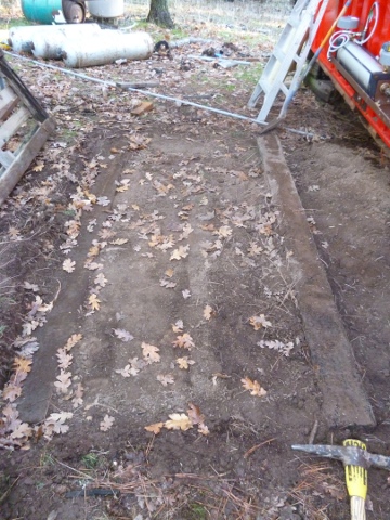
In this case, the top of the uphill tie was notably below the surface, so the final step involved using the leveling shovel to level the interior of the rectangle by relocating any above grade dirt. Good use of the removed dirt was made by using it to bed in around the ties and to fill in where the portions of the interior that were below grade. The two heavy railroad ties aren't actually connected to anything, or even to each other. Because they're not rigid, and because they're wood, they'll be able to take the vibration without being damaged as they just float with it in place.
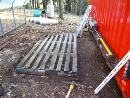
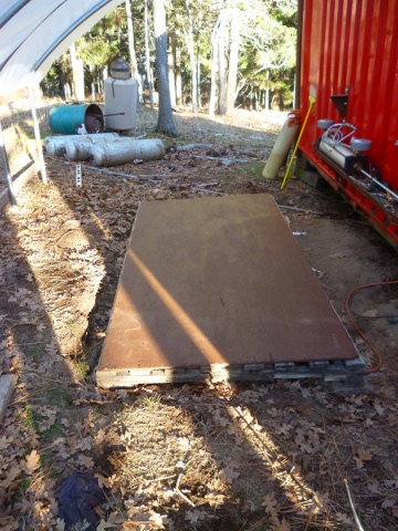
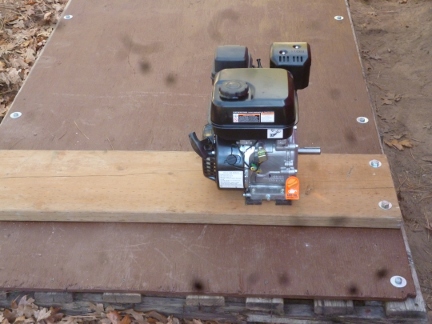
With the foundation in place, the next step was to bring in a double length pallet to rest on the two railroad ties. The palet was then covered with a sheet of 1/2" plywood. A generous amount of sheet rock screws were used to bond the plywood to the double pallet.
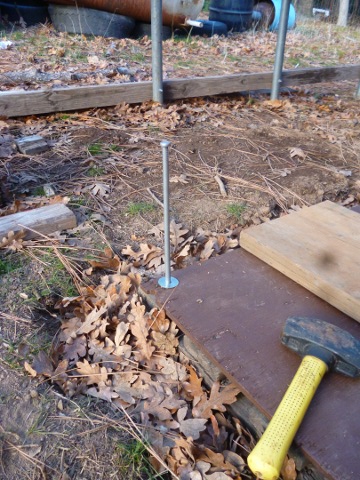
Now came the task of securing the pallet to the railroad ties its was resting on. The first step was to drill down through the pallet and into the railroad tie using a 3/8" auger bit. Then 12" long 1/2" diameter spikes were driven down through the holes and into the ties below.
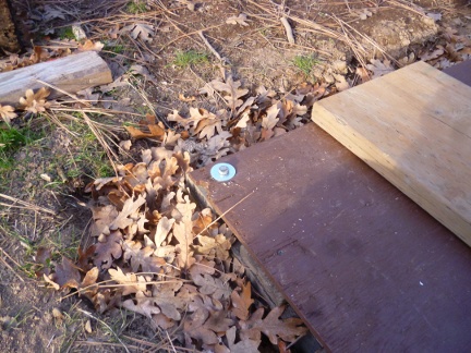
The spikes were not pounded in all the way, but were left a little loose so that the pallet could work up and down as need be in order to dampen the vibration of the motor. This attention to detail is probably overkill, but that's intentional since overkill is a key component of our design strategy.
Four spikes were driven in per side to complete the floating foundation.
|